


Today's curious story is "CAD line type"
The drawing consists of a combination of various shapes and symbol lines. In order to understand drawing features, it is necessary to read various information such as symbols and annotations, but knowing what each line has and how to apply it will help you to interpret the drawing.
 |
| <Figure 1-1 CAD line type> |
Figure 1-1 lists commonly used lines in CAD.
1. Solid Line, Thin
Typically used as dimension lines. etc,
- hatching, thread, short centerline, support line
2. Break Line
A broken line is a line used when there is no need to mark the entire part of a product. For example, when a long object such as a pipe round bar is displayed on a drawing sheet, The line.
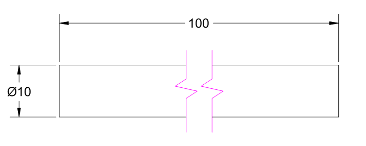 |
| <Figure 1-2 Break Line> |
Figure 1-2 is an example of a broken line.
3. Solid Line, Thick
A line that represents the shape of the shape.
 |
| <Figure 1-3 Bold solid line> |
4. Dashed line
It is also used for displaying hidden parts and projecting invisible parts.
 |
| <Figure 1-4 Hidden line> |
As shown in Figure 1-4, the treatment of invisible areas is done with a dashed line.
5. Thick hidden line (Dashed line)
This is the line used to describe the surface treatment. For example, it means heat treatment or the like.
6. Dot-Dashed line
Used for marking circle, hole, center of symmetry plane.
 |
| <Figure 1-5 Center line example> |
7. Dot-long dash line
It is used for marking when surface treatment is necessary.
8. Dot-long dash line
The dotted line is used to mark the virtual line.
It was a curious story.

0 댓글